


Top DFM Tips for Plastic Injection Molded Parts

Design for Manufacturability (DFM) is essential when developing plastic injection molded parts. Optimizing your design does not just reduce production costs but also improves part quality and ensures a smoother manufacturing process. By addressing potential molding challenges early, such as material flow, part ejection, and mold complexity, you can avoid costly redesigns and production delays. Failing to carry out DFM for your plastic parts will leave you with tooling changes, high rejection rates, and increased prices.
This blog will explore key DFM tips for plastic injection molding, including undercuts, side actions, wall thickness, draft angles, gate placement, and ejector pins. By following these best practices, you can create high-quality parts that are easier to mold while also being more cost-effective.
Avoiding Undercuts
Undercuts consist of a protruding feature of a part that makes it difficult to eject after the plastic fills the cavity. With undercuts, you are able to fill the cavity perfectly fine but it’s difficult to release from the tool. Examples include side holes, internal threads, or snap-fit joints.
To minimize or eliminate undercuts:
Redesign the Part: Modify the geometry to remove undercut features, such as replacing side holes with surface features or altering internal threads to external ones.
Adjust the Parting Line: Repositioning the mold's parting line can sometimes eliminate undercuts by allowing the feature to be formed without additional mold actions.
Incorporate Side-Actions or Lifters: If undercuts are unavoidable, use side-actions or lifters in the mold design to facilitate part ejection.
By carefully considering part design and mold configuration, undercuts can often be avoided, leading to more efficient and cost-effective manufacturing processes.

Using Side-Actions Wisely
Side-actions, also known as slides, are mechanisms in injection molds that move perpendicular to the mold's opening direction to form undercut features that cannot be produced with a straight-pull mold. While they enable complex geometries, side-actions add cost and complexity to the mold (Proto Labs).
As you can see from the image below, the cavity is pressed into the core and you need the side-action core to slide into the mold to give the end shape. Without the side-action then you would have a completely different end part.

Optimizing Wall Thickness
Achieving optimal wall thickness in injection-molded parts is crucial for ensuring structural integrity, efficient manufacturing, and high-quality end products. Uniform wall thickness facilitates consistent material flow and cooling, reducing the risk of defects such as warping, sink marks, and internal stresses.
When designing plastic parts, make sure you have consistent thickness throughout the part. If variations are necessary, transition gradually to prevent stress concentrations and potential defects.
In addition, make sure to adhere to the recommended ranges. The ideal wall thickness depends on the material used. For instance, general guidelines suggest:
ABS: 1.2 mm – 3.5 mm
Nylon: 0.8 mm – 3.0 mm
Polypropylene: 0.8 mm – 3.8 mm
Polycarbonate: 1.0 mm – 4.0 mm
These ranges will help reduce the risk of parts with quality issues.
While you might think that it’s ok to have the part thicker, you would be wrong. You also need to avoid parts that are too thick. Overly thick walls can lead to longer cooling times and increased material usage, potentially causing sink marks and internal voids.
By carefully designing wall thicknesses, you can enhance part performance, reduce manufacturing costs, and improve overall product quality.
Core-Cavity Considerations
In injection molding, the core and cavity are the two primary components that shape the final part. The cavity (A-side) forms the external surfaces, while the core (B-side) shapes the internal features. Proper design and alignment of these elements are crucial for part accuracy and mold functionality.
Here are a few considerations to consider:
Part Ejection: Design the mold so that the part remains on the core (B-side) during mold opening, facilitating efficient ejection. This approach leverages the mold's ejection system to release the part smoothly.
Shrinkage Management: Anticipate material shrinkage during cooling. Parts tend to shrink onto the core; designing with this in mind ensures dimensional accuracy and reduces the risk of defects.
Mold Alignment: Ensure precise alignment between the core and cavity to maintain uniform wall thickness and prevent defects such as flash or mismatched parting lines.
By carefully considering core and cavity design, you can enhance part quality, ensure dimensional accuracy, and streamline the manufacturing process.
Ensuring Proper Draft Angles
In injection molding, a draft angle is a slight taper applied to the vertical faces of a part to facilitate its removal from the mold. Incorporating appropriate draft angles is essential to prevent damage to both the part and the mold during ejection.
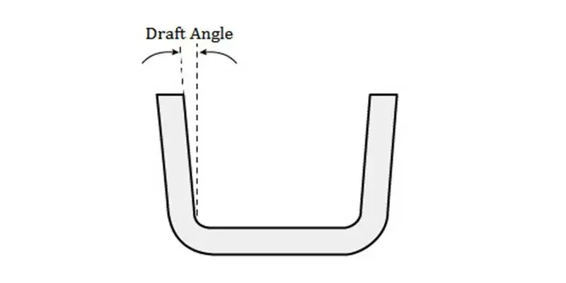
A general guideline is to apply a draft angle of at least 1° per inch of cavity depth. However, this can vary based on part geometry and material.
If you have a textured surface then it may require an additional draft to account for the surface roughness. For instance, a heavily textured surface might need a draft angle of 3° or more to ensure proper release.
In addition, different materials shrink at varying rates during cooling, affecting the necessary draft angle. Consult material-specific guidelines to determine appropriate draft angles.
By carefully designing parts with suitable draft angles, manufacturers can ensure smoother ejection processes, reduce wear on molds, and maintain the integrity of the final product.
Gate Placement for Optimal Flow
In injection molding, the gate is where the molten plastic flows into the mold cavity. Strategic gate placement is crucial for ensuring uniform filling, minimizing defects, and achieving high-quality parts.
When designing your gates, keep in mind the following:
Position in Thick Sections: Place gates at the thickest part of the part's wall thickness. This position allows the molten plastic to flow from thick to thin sections, reducing the risk of voids and sink marks.
Minimize Flow Length: Position the gate to minimize the flow length, ensuring that the molten plastic reaches all areas of the mold efficiently. This approach helps maintain uniform material properties and reduces the likelihood of defects.
Avoid Obstructions: Place gates away from cores, pins, and sidewalls that can impede the flow of plastic. However, positioning gates near features that offer slight resistance can help control flow rates and prevent excessive pressure drops during filling.
Consider Aesthetics: If the part has cosmetic requirements, position gates on non-visible or non-functional surfaces to avoid blemishes. Creating gate recesses or using specific gating methods can help hide gate marks.
By carefully selecting gate locations, manufacturers can optimize material flow, reduce potential defects, and enhance the overall quality and appearance of injection-molded parts.
Ejector Pins & Part Removal
Ejector pins are critical components in injection molding and are responsible for pushing the part out of the mold cavity. Proper design and placement of ejector pins ensure the part can be removed from the cavity without causing damage or leaving noticeable marks.
When designing the ejector pins for part removal, keep in mind the following:
Balanced Ejection Force: Arrange ejector pins to apply consistent force across the part, minimizing the risk of deformation or warping during ejection. For complex parts, increase the number of pins to distribute the force evenly.
Evaluate Pin Placement: Position ejector pins in areas with sufficient structural support, such as ribs, bosses, or thick sections, to prevent damage. Avoid placing pins on thin or delicate features that may be prone to breakage.
Surface Considerations: To maintain aesthetic quality, place ejector pins on non-visible or non-cosmetic surfaces whenever possible. This practice helps prevent visible ejector marks on the finished part.
Pin Size and Quantity: Utilize the largest feasible ejector pins to reduce the number required and distribute ejection force effectively. Larger pins provide more contact area, reducing the likelihood of leaving noticeable marks.
Avoid Obstructions: Ensure ejector pins do not interfere with other mold components, such as cores or side-actions. Proper clearance must be maintained to prevent mechanical conflicts during the ejection process.
By carefully considering the design and placement of ejector pins, manufacturers can achieve efficient part removal while also keeping the high-quality finish you require.
Material Selection
Material selection is a critical aspect of injection molding, as it directly influences the final part's properties and dimensional accuracy. Each plastic resin exhibits unique characteristics, including specific shrinkage rates during cooling, which must be considered to ensure high-quality parts.
There are many things to consider when deciding on the type of material, such as the following:
Shrinkage Rates: Plastics shrink as they cool, with rates varying between materials. For instance, polyethylene and polypropylene tend to have higher shrinkage compared to other polymers, such as polystyrene or polycarbonate. Understanding these rates is essential for accurate mold design.
Mold Design Compatibility: Molds are typically designed to accommodate the shrinkage rate of a specific resin. Switching materials without adjusting the mold can lead to parts that are out of tolerance or have dimensional inaccuracies. Therefore, if the tool is designed for the material to be polypropylene but you decide to change the material to polycarbonate after the tool is done then expect some issues to occur.
Process Parameters: Processing conditions, such as mold temperature, injection pressure, and cooling rate, significantly impact material shrinkage. For example, higher mold temperatures can reduce shrinkage by allowing the material to fill the mold cavity more completely before solidifying.
Material Testing: Before finalizing material selection, it's advisable to produce test parts using the target material. This approach helps in assessing the material's behavior during molding and its suitability for the intended application.
By carefully selecting materials and considering their shrinkage characteristics, manufacturers can design molds that produce dimensionally accurate and high-quality injection-molded parts.
Conclusion - DFM Tips for Plastic Injection Molding
Designing plastic injection molded parts with manufacturability in mind is essential for achieving high-quality, cost-effective, and reliable production. By following key DFM principles, manufacturers can reduce defects, streamline production, and extend mold life.
Each of these principles contributes to the overall efficiency and consistency of the injection molding process. Collaborating with experienced mold designers and manufacturers early in the development phase ensures that potential challenges are addressed proactively. Ultimately, thoughtful DFM practices lead to better part quality, lower production costs, and improved manufacturing efficiency.
Comments